Friday, March 31, 2017

Rover Robot Hacked to fire 4-barrel 32 Caliber Minigun.

Rover Robot Hacked to fire 4-barrel 32 Caliber Minigun.


This was an experiment to try and hack the hardware of an off-the-shelf toy "robot". It worked very well and was an interesting build.  In this article, I am going to show how this was performed and give an idea of how you can modify closed source hardware with a minimum of parts to add your own hardware
Using a Brookstone Rover 2.0 WiFi controlled Robot with a hardware hack to fire a home-made 4-barrel, 32 caliber mini gun. Each time the headlights are cycled on/off, the mini gun will fire a round out of the consecutive barrel.

Here's a demonstration of this Rover actually firing the mini gun!


If you have a Brookstone Rover 2.0 and would like to run it using a PS3 game controller and an Ubuntu (or Windows/Mac) laptop like that is shown in the video, Simon Levy has provided the Python code and and some great instructions at:


The circuit for the Rover does not really have any options to expand the hardware, so I used an 4N27 opto-isolator to hijack the headlight LED Signal that is monitored by an Arduino Nano.  Each time the Headlight is turned on/off from the controller, it fires one of the gun barrels. This method can be modified to be use on just about any RC toy that has a remote LED switch.  The schematics are broken down into 2 parts.  The first one shows how to wire the Opto-Isolator and Arduino into the Rover's Headlight LED. The second shows how to switch 4 devices (4 barrels in my case) using tip120 transistors.  I will also provide the simple arduino code that operates this hack.

 The Rover supplied enough current to turn on the individual headlight as well as trigger the opto-isolator, so I did not have to alter the rover's existing circuitry.  Just solder the opto switch onto the free solder pads on a headlight led circuit board.  Other RC device LED circuits you may have to remove the existing LED and replace it with the opto-isolator.

The rover has 4 headlight LED circuit boards along with free/open MARKED solder pads on each!  You can't ask for an easier connection!


Note: I powered the arduino using the Rover's Battery connection on the main board.  This allows the arduino to be turned on and off when the rover's power switch is turned on/off. (see photo above). The pads are clearly marked for B+ and B- for battery + and - on the Rover's main circuit board.
  B+ goes to the Nano's VIN. B- goes to the Nano's GND.

Click image for full size opto-isolator Schematic.
A couple resistors and a connection to Input pin D8 to read the signal. 5v from the arduino provides the correct voltage for the input pin (Signal high, headlight is off). That's all that is required to read the rover's headlights turn on and off.  Since it uses the opto-isolator, the arduino is isolated from the Rover's circuitry except for the same voltage supply and GND.


Click image for full size schematic.

The circuit that fires my mini gun is a simple TIP120 Darlington transistor switch.  It uses a separate power supply that has the Battery + connected to the Loads + power on J1. When the arduino D7 goes high, the TIP120 turns on and provides the ground for the circuit. Acting as a switch to complete the circuit. This circuit can be used to turn on motors, solenoids and even lasers.


Click image  for full size schematic
I repeated this circuit a total of 4 times (Digital pins D4-D7).  This allows me to treat each barrel of my mini gun as an independent device and allows the code to fire each barrel independently.

The code to detect the headlight signal and fire each of the 4 barrels is very simple and can be downloaded from here:


 #define beam 8 //Digital signal pin # from opto-isolator  
   
 void setup()   
 {  
  Serial.begin(9600);  
  pinMode(beam, INPUT); //Read signal from headlight   
  for(int bar = 4; bar <8; bar++)  
  {  
  pinMode(bar, OUTPUT); //Open digital pin 4-7 for output (barrel triggers)  
  }  
 }  
   
 void loop()   
 {  
  for(int bar = 4; bar <8; bar++) //"bar" is barrel 1-4 on digital pins 4-7  
  {  
   while(digitalRead(beam)==1){ //do nothing while headlights are off (digital pin 8 signal)  
    delay(100);}  
   while(digitalRead(beam)==0){ //if headlights are on, fire next barrel on next digital pin  
    digitalWrite(bar, HIGH); //trigger ignitor on bar digital pin "bar".  
    delay(3500); //delay 3.5 seconds to reach high temp  
    digitalWrite(bar, LOW); //turn off ignitor on digital pin "bar"  
   }  
   digitalWrite(bar, LOW);  
  }  
 }  

  The code is commented and should be self explanatory. It monitors pin 8 for the headlight to be on, then it cycles through pin 4-7 to fire each barrel each time it receives the signal.

As mentioned, this circuit can be easily used on other remote control toys or any device that uses an LED to indicate an ON/OFF state.
  As for the mini cannon itself and the technique/design to fire it, I am not going to discuss how it was made since it is extremely dangerous, but could be deadly.  If you have the proper tools and knowledge to accomplish this build, then it would be a very simple project. DO NOT ATTEMPT TO RECREATE THIS FULL PROJECT WITHOUT PROPER TRAINING and TESTING!

Sunday, December 4, 2016

Aluminum Casting X-Y Axis Acme Nut Trap from 3D printed models.


X axis acme nut trap. 

I am using 3/8" acme rods and nuts for my X and Y axis.  Nothing I could find would fit my custom cnc build,  so I decided to 3D print some models out of ABS and cast them out of scrap aluminum. 

Models and Machined acme nut Traps. 

 After casting the parts in a sand mold,  I machined them on a 12" drill press using an X-Y table and a CNC straight cutter.  Slight modifications to make them fit exactly how I needed them. 

Y Axis acme nut trap. 

Right now there are only a couple washers/nuts locking the nut to the trap.   Once the cnc is up and running  I will machine a couple clamps to lock them to the nut traps. 

Thursday, November 17, 2016

Aluminum Casting CNC Z-axis carriage


It's been a while since my last post, but there is a really good reason.  I was building a foundry and teaching myself mold making for aluminum casting.  The real hard part was getting a 3d ABS print to create a clean mold.  A problem since it is not a smooth surface.  I found a solution and will be making another post to explain how to do it.

  The video above shows the casting process for 1 of the 6 parts that make up the Z-axis/carriage for my CNC.  It included the spindle mount I designed for the ryobi circle cutter spindle.  There are 2 smooth rod holders for 8mm rods, 2x bearing mounts for 15mm OD 8mm ID bearings.
  It turned out really well with very tight tolerances. No play at all.

Sand cast mold of the 3d printed part.


Comparison of the 3d part alongside the aluminum casting.


Aluminum Cast smooth rod mounts.


The complete Z-axis carriage assembly.


Almost to the electronics. Just have to install the Acme screws/nuts, Design mounts for the limit switches. Then I can start on the electronics assembly/setup.  It is coming along really well.


Tuesday, April 5, 2016

Recycled parts for my CNC


I am all about reusing,  recycling junk in my builds.  The cutter/spindle motor is no exception.   I've been shopping around for my spindle motor for my cnc.  Estimated this would cost me $70-$150 for this part alone.  Then while looking for some hardware in my junk box,  I came across the perfect motor! 
This is a Ryobi SS180 speed saw/circle cutter that I purchased as part of a Ryobi tool package almost 10 years ago and has never been used.  I cracked it open and found the perfect spindle for my cnc.  Perfect especially since it is FREE! 


The motor is rated at 26,000 @ 18v dc.  I can hook this up to the cnc controller or more likely,  I will connect it to it's own DC PWM controller for manual speed control.  It has a 1/8" and 1/4" reversable collet sleeve already on the shaft as well as a high speed bearing.  It appears the shaft is hardened tool steel,  so it should work  very well.  Also is air cooled (fan). 
 Mounting threaded screw holes on the body and the beefy 32mm bearing on the shaft will make mounting extremely easy. Never know when you will be able to use something in your junk drawers!


  Another new addition to my shop is a Grizzly G8750 compound slide table for my drill press!  Until now I have been doing all my metal machining freehand.  I wish I had this when I started my build.  It makes everything so much easier and precise! Next upgrade will be a new drill press.


Bearing and motor mounts in t6061 aluminum are so much more precise with the X-Y compound table!  It's a dream! 


Tuesday, March 22, 2016


Minor update,  installed the 5/8" acme screw for the X axis using a 3/4" push bearing in the uprights.  NEMA 17 motor connected with a 6mm to 5/8" coupler. .  Z plate has 2040 openbeam installed.  Next step is to mount the Y axis acme bolt,  motor and hardware.  


This is the current state of my CNC build. The X and Y axis are complete, using 12mm Rods and bearings.  I am waiting for delivery of some 20x40mm Openbeam to start the build on the Z axis.

  The Z axis will be removable to swap different cutters/heads that can easily be bolted onto the 2040mm openbeam..  After that, the only parts that remain are the 5/8" threaded rods and the electronics.

The initial setup will be Sainsmart tb6560 4 axis 3.5amp controllers using 3x 17hs24-2104s Stepper motors and Mach3 Controller software  running on an old IBM Thinkpad (for the serial port) running WIN-XP. Not sure of the cutter head that will be used, but initially going to use a palm router with an electronic speed control unit.

Friday, November 6, 2015

Favorite Build, CNC


Home Made CNC Build

 This is my absolute favorite project I have ever worked on!  After 3d printing and customizing the CYCLONE PCB CNC,  I decided it was time to go onto a project I have dreamed about starting for several years.  A full size CNC with a coolant pump that is capable of cutting Aluminum! 
  This is the first axis (Y axis) installed on the 1"x1" square tube (1/8" thick)  steel frame.  The current stats are 30" Y-axis (length),  a 20" X-axis (width)  and the Z-axis (height)  will be adjustable by a changeable carriage.  My current goal is going to be a 6" cutting height.  
  The frame sides are welded.  The 3/8" case hardened rods are anchored at the ends in aluminum blocks with the steel tube ends mounted to the aluminum blocks.  The bed is attached to the steel tube ends.  This allows the bed and rail to be locked at a specific distance and will be true throughout the entire Y-axis! 

  The result is the Y-axis rods are locked into the bed,  even if the frame was off.  Even though the sides of the frame are spot welded,  almost every other part is being attached with black oxide hex nuts and tapped/threaded holes.  The bed is standard 20mm x 60mm openbeam t-slot aluminum. 
  My design is made to lock one part into the next,  before being screwed together.  BUT,  if any part were off and needed adjusting,  they can easily be shimmed.  That is another design goal with this project.  I want everything to be replaceable/upgradable.  For example,  I am starting with NEMA 17 motors (because I already have them.),  but think I will be upgrading almost immediately to NEMA 23 for aluminum.  The Z-carriage will be able to swap out for different heights and cutters. 
  Next will be building the X-axis.  Hope it goes as well.  Check back for updates. 

Thursday, August 13, 2015

Cyclone PCB cnc


I've been a little sidetracked with a cnc build lately.  This is a wonderful first cnc project using a standard Arduino Mega 2560 with Ramps 1.4, running Marlin as the gcode controller.   I printed the parts in a combination of black PLA and red ABS. Printed on a modified Prinrbot simple maker's edition. 
  This is the cyclone v2.1 pcb cnc which is located at https://github.com/carlosgs/Cyclone-PCB-Factory/tree/v2.1
 I managed to build it before there were a detailed instruction file.  But they have recently added it to:  http://reprap.org/wiki/Cyclone_PCB_Factory/build
 There is also a support group located at: https://groups.google.com/forum/m/#!forum/cyclone-pcb-factory
   I'll try and post a video of it cutting some shapes in to plexiglass on the next few days.  Be sure to print the gears out of ABS since PLA will not last more than a few runs. 

Saturday, June 6, 2015

Lawnbot's off road test drive video!


 Here is an updated video of the actual lawnbot running on the lawn.  (water rationing in southern Calif.  So not much actual lawn!)
 Initially it kept stalling out a couple times a minute.  Pause for just a second.  I thought it was pulling to many amps and the code was shutting the circuit down for safety.  This was not the case.  It was actually reading the radio to soon and was dropping packets.  This result in a no connection result that put the code into a loop till it received valid data from the transmitter.
  I did find that the current readings were topping out at 10amps (each motor)  with a quick change of directions.  So I installed the - 30 to +30amp current sensors and have them safety checking at about 15-17amps. I'll check after the added weight of the propane motor and it's electric starter motor,  to adjust it any further.  Right now the pwm is limited to 90 out of a possible 255, so there is still a lot of performance possible in this build!
  In the video,  you will notice that it manages to drive up and over the border bricks.  This was a surprise since I didn't think it had that kind of torque/power.  Still quite a bit of fun left in all these recycled scraps!
  Motor mounts for the propane motor and it's custom starter motor are next on the list (after weight/amp tests).  So be sure to check back.  Any questions,  please let me know!

Wednesday, June 3, 2015

Lawnbot finally moves!


06/03/2015
  It's been a while since I have been able to work on this project,  but it is now sitting in the middle of my living room for some major upgrades and testing!  (and my wife is still talking to me?!?)
  I had a 30amp circuit breaker attached.  The first time I tested it, It blew the circuit breaker under load.  So I installed 2 ACS711EX Current Sensor Carrier -15.5A to +15.5A.  The PWM is set to max out at 60 (out of a possible 255) and with the current sensors shutting down the current draw at 13amps per motor,  it seems to run quite well.  Higher Current supply or different motors will be a future upgrade after I get everything running correctly.
  A couple other upgrades you may notice from the video: it has a separate wireless control that will be able to take control during autonomous activities or in an emergency.  The remote is made with an analog thumbstick/joystick,  an arduino nano clone,  4x16 lcd display and an nrf24l01 2.4ghz radio (2nd one on the lawnbot).
  I also added a mosfet and relay switch to allow the lawnbot's mega2560 to turn the high voltage/current to the motor controller.  The mega does a simple voltage check to ensure there is enough of a charge. If so will turn on the motor controller's,  motor current feed.  It does this with a simple voltage divide reading on analog pin 0.
  With the upgrades of the current sensors,  relay,  nrf24 radio,  new main power switch,  circuit breaker and various leds,  it has been rewired a couple dozen times and has some new 3d printed parts.  I think the controller will outgrow the enclosure soon,  so I may have to design another mount.  I'll try to get some newer pictures in the next few days.  (already much different than what is shown in the video above!)
  The next steps are to test the failsafe controller by driving it around the lawn for a bit. The living room is only big enough to do some parallel parking tests.
  If that works out well,  then I will start building a custom mount for the propane motor and it's starter motor as well.  These will always be manually controlled for safety reasons!

Wireless controller before 3d printed housing.  Uses external 5v USB batter

A view of the control assembly from a few weeks ago.  When the wires were still manageable! 

Monday, January 26, 2015

3D Printer Linear Motion without Linear Bearings!

 I currently use several modified Printrbot Simple Maker's Editions. They are very solid machines and make some impressive and fast prints. My largest print size is 200mm x 320mm. Roughly 8” x 14".
  The one thing that is a constant battle for higher speed prints is slop or flexing parts during the movements. I started experimenting with different materials to use in place of linear bearings for use in 3d printing. Although 8mm linear bearings and case hardened rods are the go-to solution, they still have play that is evident in the prints (especially when changing direction)..
  One quick, possible solution for my existing printers are the small round parts in the pictures. They are 8mm I.d. x 10mm x 10mm linear bushings. The are self lubricating bronze linear bushings with a hardened carbon steel outer casing and a PTFE (Teflon) inner liner. Extremely nice fit with no play, but they will require some new mounts to be fabricated to fit my existing bearing mounts.

The white part on rails is a test for my custom designed printer. The plastic is also self lubricating, but is HDPE. 
  I am very excited about this test as it is smoother than the bearings could ever hope to be and will easily be fabricated so there will be no play when mounted correctly.
  It's 5/8” thick HDPE and has had all 4 sides routed top and bottom, leaving a 3mm tab that fits snugly into the 3mm screw rail of  15x15 mm extruded aluminum (openbeam v2.1).
   This is an idea that I hope to develop in my custom printer and maybe even for the CNC machine I have been planning for the future.


  The last item is a roll of PTFE tape. I had considered using it to line the edges of an aluminum plate that could also run in the extrusions rail with HDPE wheels to provide side pressure, removing all play. That is something I will be trying and sharing the results here as well.
  It may be necessary to use aluminum/Teflon combo over the HDPE glide depending on how well my ideas work out to prevent heat creep on the heated bed and extruder mount. HDPE is my material choice for these projects. Wonderfully smoother linear movements without bearings.

Thursday, November 13, 2014

New hardware including 3d Printers are being added!

I  got extremely sidetracked while waiting for a delivery of 10 ultrasonic sensors from China.  It basically took 3 months before the shipper would agree they were lost in transit.  In the mean time,  I received a Christmas gift that took over 100% of my hobby time.  A Printrbot Simple 2013 maker's edition 3D printer.  Since that time I have completely changed the design of that original printer and built 2 more.
  I started designing mod files and even recreating the original Laser-cut DFX files into Printable STL format. If you have a printer you can print your own 2014 Printrbot Simple 1405. If you don't you can commission an owner to print you one or even use a local 3d print service.  Those and all my files can be located at  http://www.thingiverse.com/metaled/designs
  I have a ton of subjects I would like to share hints and tips for.  Don't get me wrong,  I have ordered new Ultrasonic Sensors and do plan to continue sharing that robotics project.  But I  also plan to share Raspberry Pi,  PcDuino,  Arduino,  Intel Edison and lots of electronic circuits with the Lawn Mower Robot assembly!
  I'll try to find time to share as much as possible and if you have any questions,  please feel free to ask in the comment sections!


Sunday, October 20, 2013

Brains behind Arduino Lawn Mower!


Finally got a delivery from China.  It is the new Arduino Mega 2560 R3 compatible MCU along with a the v2 Sensor Shield.  (this combination had the same pin to usb short I discussed in an earlier post.  Be sure to check that post for the fix or it will fry your mega 2560! (Arduino Mega 2560 shorts against v2 Sensor Shield)
 It took a couple weeks to be delivered,  but the price is less than a quarter of what the cheapest price vendors are offering it here in the U. S..  Not only do a lot of local vendors order them from china,  but a lot of auction sellers will take your money and have it drop shipped from china.  Well worth it to do some research and cut out the middle-man! 


Now that I started to put the components into the battery box,  it is getting very tight with the new SLA 12Ah 12v battery.  The solution is to build a multi-level control board that will slip right in beside the battery. Seems like it works very well,  but it might get a little tight after I start adding sensors and more wiring. 

Thursday, October 3, 2013

Hobby RC remote for testing the Lawnbot!

I've been stuck indoors, unable to work on the mechanical parts of our robotic lawn mower.  I took advantage of this time and wired a Futaba FP-R127DF 7 channel Receiver to an Arduino Uno r3 and wrote a few lines of code to see if I could get it to read the signal from a Futaba T6XH-Super PCM1024 6 channel transmitter.  Was a lot easier to get the Arduino to display the signals than it is going to be for me to figure out what they all are.  This is a programmable aircraft/helicopter remote with settings for just about everything.  Ailerons, flap, Swash Plates and mixing of all the signals.  Wish it was a standard RC car remote!  It's going to take some research to program the transmitter.  With what I do know now, I believe I can get it driving the bot. 
 I started out the day knowing nothing about how to read or interpret rc hobby remotes.  I searched and found a real nice tutorial over at sparkfun.  Wasn't as complete as I thought,  but there is additional info in the comments that will help get it working with dual motor controllers.  The actual page is: https://www.sparkfun.com/tutorials/348
 BTW, not sure if the Raspberry Pi running Raspbian allows for enough time slicing in the multi-tasking to be able to poll the serial ports (usb)  for an rc transmitter combo.  I originally started using the Pi to program the Arduino as I always do.  When I opened the serial port monitor to view the signals, the cpu bogged down and brought the entire system to an absolute crawl at 9600bps.  Made it unusable.  Was forced to bring out another machine with an OS that I loathe! If it weren't my kids, I would install linux on it.  If you were to really delay the polling, you may be able to read it, but I would really check into other OSs or distributions if you want to use it with the Pi.  This is one of the reasons I  will be using the arduino with the Pi on this robot. 
 Tomorrow I hope to post some new updates on the chassis.  At the latest I hope to have something actually moving my the end of next week!  
 I also updated the current hardware page.  This is really starting to run together.  I think it's time to separate the parts by project.  That way if you are trying to duplicate something,  you will know exactly what I  did it with. 

Tuesday, October 1, 2013

Large mower-robot chassis progressing quickly !

Here's a quick update since I haven't posted in a bit.  Work is going on daily.  At least a couple hours a day is what I have been trying for.  Lately I  have been working on getting a physical chassis up and running.  What is pictured is a first mock-up of my 3 wheeled mower bot.  
The 2 rear wheels are salvaged, geared drive, dual 12v, 25 amp motors.  Taken from a kid's power wheels ride on jeep.  Along with the dual 45amp mosfets driven H-bridge should be more than enough to drive this bot through any urban environment . 
 The cutter motor is a 25cc, 4 stroke propane string trimmer (weed whacker) motor.  I had built the system around the string trimmer's 18" inch cutter head, but the body size of 18x24 inches is extremely large for my yard and would not only cut the lawn in a couple passes, but prevent me from maneuvering in the tight areas.  So I believe I  will not only shorten the cutter head, but also the overall size by about 2/3rds.
  The next step is to mount the battery box and some of the computer equipment so I  can start testing the base with a 6 channel remote control.  I will be sure to post some videos of this step as well. 
 The next hurdle is going to be cutting up the motor's clutch housing and fabricating a cutter head drive.  Obviously I won't be able to use the 8 foot drive shaft that came with the weed whacker. 
  So anytime I am not posting,  it's not that I have given up on any of this project!  It's more like I am so involved and barely have time to do anything but work on this bot.  I really want it to move forward quickly and have a working, remote controlled chassis in the next couple of days!  (did I mention a contractor has the front of my house torn off at the moment?  Ah,  Busy days!) 

Sunday, September 22, 2013

Raspberry Pi tablet using Tightvnc and Remote Ripple.

Yesterday I showed you how to convert an inexpensive LCD monitor to be powered and run with the Raspberry Pi. My intention for that screen is to run a custom python program which will monitor sensor data and system status of my robot.  But it is much too small for everyday use and I  really don't want to plug it into the HDMI monitor every time I need to change one line of code.  The solution for me is to run a TightVNC server on the Raspberry Pi and Remote Ripple (from the creator of TightVNC. )  on my Nexus 10 running Android.  I can connect to the RPI from Windows, Macintosh, Linux, Android or any computer running a VNC Client program over WiFi. You can then run any program,  change files,  update the system, reboot or halt the RPI as if you were connected to it with a keyboard,  mouse and local monitor with any computer running the client software.  Even a Nexus 10 Tablet! 
So how do you do it? 

 I installed it using the instructions here: http://elinux.org/RPi_VNC_Server


TightVNC is available for free at Tightvnc.com contains the client and server software, is available for free and works on most platforms (except android) .  Remote Ripple client software does work on Android,  requires a very small license fee and is available from the Play Store. 

Friday, September 20, 2013

Hack 4.3 inch tft display to run on the Raspberry Pi's 5v DC supply!


I purchased one of the inexpensive 4.3 inch tft lcd display to use with my Raspberry Pi/Robot. It is set up for 12v DC Automobile voltage, but the hardware can be hacked to run on 5v DC power.  The same power as the USB input on the Raspberry Pi and the logic supply on my motor controller.  I did a search and found instructions for other displays,  but not for the specific one I had purchased.  No brand name on the packaging.  It is model number BWCMO363 and is titled " 4.3'' Color TFT Car Monitor Support 480 x 272 Resolution + Car/Automobile Rear-view System Mirror Display Monitor" on Amazon that uses  the xl1509-5.0 voltage regulator.  Note: do not do any of the following unless you are familiar with electronic components and comfortable with the procedures described.  Altering the components can damage or destroy your display. 
I found the data sheet and confirmed that pin 2 was the 5v out.  Unlike other instructions, I just want to change the power requirements from 12v to 5v.  I am not swapping in a USB cable or any other mods, so it is not necessary to unsolder the voltage regulator chip or even disconnect any other wires except the 12v + Red wire.  We do not need to disconnect the ground since I  am using this cable's Black/ground wire. 
(xl1509-5.0 located center, far right on the circuit board. 
Only 8 leg IC on the board))

This second photo you can see that I moved the red wire from the cable connector on the breadboard.  I moved it over to pin 2 of the xl1509-5.0 voltage regulator and carefully soldered it to the pin 2 leg.  Since there is no longer a voltage in feed,  the regulator should be dormant and does not need to be removed or altered. 


This is my first solder attempt with surface mount components.  As you can see i n the photo above,  this is a very fragile procedure.  I am pointing with needle nose tweezers! My tip of the soldering iron covers at least 2 legs of the voltage regulator.  So just be prepared! 


Since I left a long lead on the wire (less than a 1/8th inch) exposed,  I  put electrical tape above and below the wire to insulate it.  Also, there is no strain relief for the input wires.  (Solder is the only thing keeping it connected to the monitor!)  I used a zip-tie,  tightened around the wire inside the case.  Cut off the tail and when it is closed up, the cable will snap before the solder joint comes under any stress. 


Before closing it up or applying any power, check your connections.  Then the only thing to do is connect it and confirm it works (another note on this model,  connect a video signal/raspberry pi.  Otherwise, without a signal it will not look like any power is connected!) 


It's up and running!  That is my desktop from my Raspberry Pi displayed on this little 4.3 inch tft screen and both of them are running on a regulated 5 volt dc power supply!  The actual monitor I purchased is listed as :

model number BWCMO363 
4.3'' Color TFT Car Monitor Support 480 x 272 Resolution + Car/Automobile Rear-view System Mirror Display Monitor on Amazon.  

Note from the reviews: the model number stays the same,  packaging and design (menu buttons)  do change. 

Thursday, September 19, 2013

Repair Terminals on Hobby DC Motors.


A lot of people think the motor is destroyed when the fragile brass terminal connector that connects the wire to the motor's brush tears off. It happens all the time from wear and tear or even from disconnecting a terminal plug when they are brand spanking new.  Most times there aren't replacements available for a darn good motor that has years of service ahead of it.
  Here is a quick and dirty fix which is not only a temporary fix, but could be way more secure than the original tab ever was.  First, most often it breaks off at the motor frame and there is no metal to solder anything to. If you are lucky, you have a small gap wide enough to insert a couple strands of thin (stripped 24 gauge or smaller) solid copper wire.  But most there will be no way to clean the existing metal.  Lets change that! (If you can get away without drilling, don't drill! If you get to aggressive, it can destroy the brush terminal!) Take the smallest drill bit you can find, most often that will be 1/16th of an inch. If possible, go even smaller with specialty bits.  We're not drilling through the case, so take it slow with a hand drill or drill press.  I used a hand driven twist drill since you just want to open up/clean the area beside the motor's connector enough for a couple pieces of thin copper wire.
You want to drill straight down beside the existing brush/terminal connection. A power drill will drill a hole too quick and chew the brass brush to bits. I fit 4 small pieces of solid strand copper wire beside the broken brass terminal. Then solder the brass and copper together making a new solid tab. That's it.  Test your motor and you are good to go!
This motor required that both terminals be repaired. Works as good as new!
If you notice the circuit board in the upper photo with 8 mosfet and close to 30 transistors. Our new dual 45 amp motor controller for the upcoming robot! Lots of good stuff coming, stayed tuned!


Monday, September 9, 2013

Homemade GPIO breakout for the Raspberry Pi / PiFace!


My home made adapter allows access to all the GPIO pins while using the PiFace! 

Problem: I have a Raspberry Pi with a Pi Camera.  I would like to install a PiFace to control some of the robot's parts direct from  the Raspberry Pi, but I would also like access to the GPIO pins so I  could also add an arduino via I2C or even SPI.  The Piface does not have a pass-through port or any access to individual GPIO pins (even though you can use 4 PiFace boards together, there is no way to connect them to each other or add any additional hardware.)  I would love to use the PiFace with any other GPIO hardware! 
  My solution: a few inches of ribbon cable,  2x 26 pin (2x13) female plugs and 1x 26 pin (2x13) male plug. A couple dollars and the PiFace is shifted up and a little to the left,  no longer crushing the Pi Camera's cable.  It also allows me to use my original Pi case (can't be used with the stock PiFace) and now I have full access to all 26 pins of the Pi's GPIO port. 
 Tomorrow I will need to mount the board with a couple well placed plastic bolts since the PiFace does not have mounting holes (relied on pin and socket electrical connection of the GPIO to hold it in place!)  This arrangement is so much better than the original configuration!  One added benefit is the space between boards.  I think I will take advantage of it to mount a cooling fan to provide airflow between both boards. 
 You can modify this in many ways,  you could run several male or female plugs to make several GPIO sockets or you could terminate it on a circuit board as I am and build a custom circuit/controller for the Pi.  Make your own sensor shield or just relocate add-on boards.  Very easy and very inexpensive! 

 Tomorrow I plan to assemble a level shifter onto the board shown connected to the GPIO cable.  This will connect an arduino board. I will also start designing a power supply to power the 3 different boards (Raspberry Pi, Arduino 328p and even a Mosfet h-bridge motor controller that is on a slow boat from China.. Literally!  4-6 weeks delivery from China!!!) 
  If it isn't clear what I am doing,  I have some grand plans for a remote robot using both the Raspberry Pi and Arduino.  The build gets bigger with each piece I complete,  so I am going to try and slow it down and get the test platform working well (via Radio Control) and then I  will move on to sensors, communication and automation. 
  
 As always,  if you have any questions on any part of this build, or you have any info that you think will make this easier (or any suggestions), please feel free to comment. 


Saturday, September 7, 2013

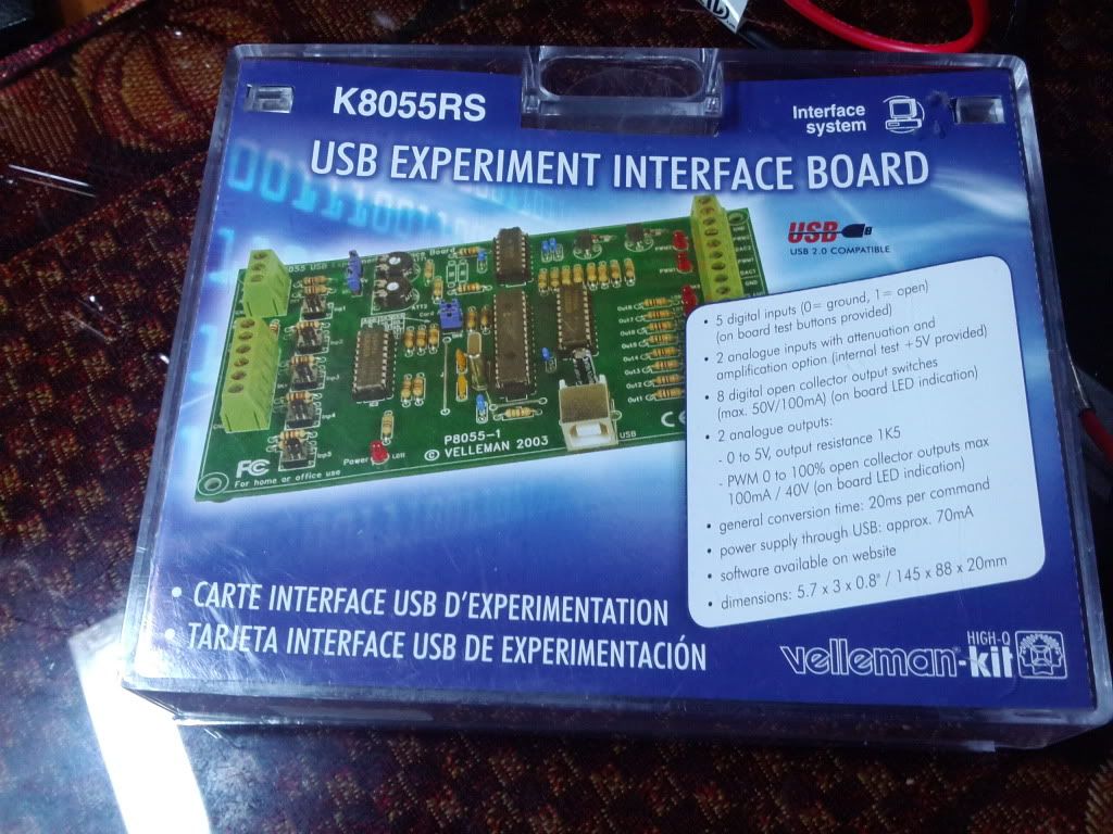
Assembled the k8055 USB controller board!

Completed the assembly of the k8055 USB controller and Experimentation board.  Got it running and tested on my  laptop.
 It seems to be operating properly and tested well.  The next step is to get a Raspberry Pi configured for this controller.  I hope to have it set up and running tests on controlling robot hardware and processing sensor data direct from it this weekend.  I also hope to share some of the harder steps and some videos on creating circuits for use by not only the k8055, but direct sensor processing via the Raspberry Pi's GPIO port as well.

Thursday, September 5, 2013

Robotic power supplies and Raspberry Pi USB controller!

I haven't posted here in a while since I  have not played with my Raspberry-Pi much.  I have been working on a couple arduino controlled robots and this week I made a nichrome plastic bender that is powered by a computer atx power supply that was converted into a robotics lab power supply with extreme accuracy in 1.25-11 volts DC using a LM350 voltage regulator IC.  I'll add some pictures of that below. 
  I had planned to add my Raspberry Pi to the Arduino robot via I2C and a level shifter.  But I think I may have found a way to make the RPI have more direct control.