Sunday, September 22, 2013

Raspberry Pi tablet using Tightvnc and Remote Ripple.

Yesterday I showed you how to convert an inexpensive LCD monitor to be powered and run with the Raspberry Pi. My intention for that screen is to run a custom python program which will monitor sensor data and system status of my robot.  But it is much too small for everyday use and I  really don't want to plug it into the HDMI monitor every time I need to change one line of code.  The solution for me is to run a TightVNC server on the Raspberry Pi and Remote Ripple (from the creator of TightVNC. )  on my Nexus 10 running Android.  I can connect to the RPI from Windows, Macintosh, Linux, Android or any computer running a VNC Client program over WiFi. You can then run any program,  change files,  update the system, reboot or halt the RPI as if you were connected to it with a keyboard,  mouse and local monitor with any computer running the client software.  Even a Nexus 10 Tablet! 
So how do you do it? 

 I installed it using the instructions here: http://elinux.org/RPi_VNC_Server


TightVNC is available for free at Tightvnc.com contains the client and server software, is available for free and works on most platforms (except android) .  Remote Ripple client software does work on Android,  requires a very small license fee and is available from the Play Store. 

Friday, September 20, 2013

Hack 4.3 inch tft display to run on the Raspberry Pi's 5v DC supply!


I purchased one of the inexpensive 4.3 inch tft lcd display to use with my Raspberry Pi/Robot. It is set up for 12v DC Automobile voltage, but the hardware can be hacked to run on 5v DC power.  The same power as the USB input on the Raspberry Pi and the logic supply on my motor controller.  I did a search and found instructions for other displays,  but not for the specific one I had purchased.  No brand name on the packaging.  It is model number BWCMO363 and is titled " 4.3'' Color TFT Car Monitor Support 480 x 272 Resolution + Car/Automobile Rear-view System Mirror Display Monitor" on Amazon that uses  the xl1509-5.0 voltage regulator.  Note: do not do any of the following unless you are familiar with electronic components and comfortable with the procedures described.  Altering the components can damage or destroy your display. 
I found the data sheet and confirmed that pin 2 was the 5v out.  Unlike other instructions, I just want to change the power requirements from 12v to 5v.  I am not swapping in a USB cable or any other mods, so it is not necessary to unsolder the voltage regulator chip or even disconnect any other wires except the 12v + Red wire.  We do not need to disconnect the ground since I  am using this cable's Black/ground wire. 
(xl1509-5.0 located center, far right on the circuit board. 
Only 8 leg IC on the board))

This second photo you can see that I moved the red wire from the cable connector on the breadboard.  I moved it over to pin 2 of the xl1509-5.0 voltage regulator and carefully soldered it to the pin 2 leg.  Since there is no longer a voltage in feed,  the regulator should be dormant and does not need to be removed or altered. 


This is my first solder attempt with surface mount components.  As you can see i n the photo above,  this is a very fragile procedure.  I am pointing with needle nose tweezers! My tip of the soldering iron covers at least 2 legs of the voltage regulator.  So just be prepared! 


Since I left a long lead on the wire (less than a 1/8th inch) exposed,  I  put electrical tape above and below the wire to insulate it.  Also, there is no strain relief for the input wires.  (Solder is the only thing keeping it connected to the monitor!)  I used a zip-tie,  tightened around the wire inside the case.  Cut off the tail and when it is closed up, the cable will snap before the solder joint comes under any stress. 


Before closing it up or applying any power, check your connections.  Then the only thing to do is connect it and confirm it works (another note on this model,  connect a video signal/raspberry pi.  Otherwise, without a signal it will not look like any power is connected!) 


It's up and running!  That is my desktop from my Raspberry Pi displayed on this little 4.3 inch tft screen and both of them are running on a regulated 5 volt dc power supply!  The actual monitor I purchased is listed as :

model number BWCMO363 
4.3'' Color TFT Car Monitor Support 480 x 272 Resolution + Car/Automobile Rear-view System Mirror Display Monitor on Amazon.  

Note from the reviews: the model number stays the same,  packaging and design (menu buttons)  do change. 

Thursday, September 19, 2013

Repair Terminals on Hobby DC Motors.


A lot of people think the motor is destroyed when the fragile brass terminal connector that connects the wire to the motor's brush tears off. It happens all the time from wear and tear or even from disconnecting a terminal plug when they are brand spanking new.  Most times there aren't replacements available for a darn good motor that has years of service ahead of it.
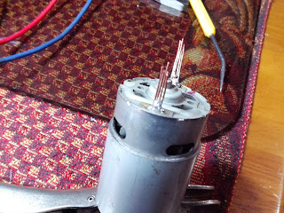
  Here is a quick and dirty fix which is not only a temporary fix, but could be way more secure than the original tab ever was.  First, most often it breaks off at the motor frame and there is no metal to solder anything to. If you are lucky, you have a small gap wide enough to insert a couple strands of thin (stripped 24 gauge or smaller) solid copper wire.  But most there will be no way to clean the existing metal.  Lets change that! (If you can get away without drilling, don't drill! If you get to aggressive, it can destroy the brush terminal!) Take the smallest drill bit you can find, most often that will be 1/16th of an inch. If possible, go even smaller with specialty bits.  We're not drilling through the case, so take it slow with a hand drill or drill press.  I used a hand driven twist drill since you just want to open up/clean the area beside the motor's connector enough for a couple pieces of thin copper wire.
You want to drill straight down beside the existing brush/terminal connection. A power drill will drill a hole too quick and chew the brass brush to bits. I fit 4 small pieces of solid strand copper wire beside the broken brass terminal. Then solder the brass and copper together making a new solid tab. That's it.  Test your motor and you are good to go!
This motor required that both terminals be repaired. Works as good as new!
If you notice the circuit board in the upper photo with 8 mosfet and close to 30 transistors. Our new dual 45 amp motor controller for the upcoming robot! Lots of good stuff coming, stayed tuned!


Monday, September 9, 2013

Homemade GPIO breakout for the Raspberry Pi / PiFace!


My home made adapter allows access to all the GPIO pins while using the PiFace! 

Problem: I have a Raspberry Pi with a Pi Camera.  I would like to install a PiFace to control some of the robot's parts direct from  the Raspberry Pi, but I would also like access to the GPIO pins so I  could also add an arduino via I2C or even SPI.  The Piface does not have a pass-through port or any access to individual GPIO pins (even though you can use 4 PiFace boards together, there is no way to connect them to each other or add any additional hardware.)  I would love to use the PiFace with any other GPIO hardware! 
  My solution: a few inches of ribbon cable,  2x 26 pin (2x13) female plugs and 1x 26 pin (2x13) male plug. A couple dollars and the PiFace is shifted up and a little to the left,  no longer crushing the Pi Camera's cable.  It also allows me to use my original Pi case (can't be used with the stock PiFace) and now I have full access to all 26 pins of the Pi's GPIO port. 
 Tomorrow I will need to mount the board with a couple well placed plastic bolts since the PiFace does not have mounting holes (relied on pin and socket electrical connection of the GPIO to hold it in place!)  This arrangement is so much better than the original configuration!  One added benefit is the space between boards.  I think I will take advantage of it to mount a cooling fan to provide airflow between both boards. 
 You can modify this in many ways,  you could run several male or female plugs to make several GPIO sockets or you could terminate it on a circuit board as I am and build a custom circuit/controller for the Pi.  Make your own sensor shield or just relocate add-on boards.  Very easy and very inexpensive! 

 Tomorrow I plan to assemble a level shifter onto the board shown connected to the GPIO cable.  This will connect an arduino board. I will also start designing a power supply to power the 3 different boards (Raspberry Pi, Arduino 328p and even a Mosfet h-bridge motor controller that is on a slow boat from China.. Literally!  4-6 weeks delivery from China!!!) 
  If it isn't clear what I am doing,  I have some grand plans for a remote robot using both the Raspberry Pi and Arduino.  The build gets bigger with each piece I complete,  so I am going to try and slow it down and get the test platform working well (via Radio Control) and then I  will move on to sensors, communication and automation. 
  
 As always,  if you have any questions on any part of this build, or you have any info that you think will make this easier (or any suggestions), please feel free to comment. 


Saturday, September 7, 2013

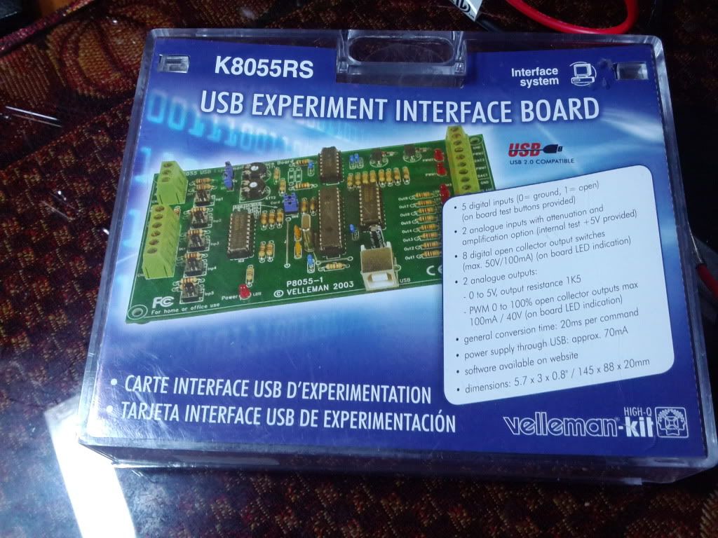
Assembled the k8055 USB controller board!

Completed the assembly of the k8055 USB controller and Experimentation board.  Got it running and tested on my  laptop.
 It seems to be operating properly and tested well.  The next step is to get a Raspberry Pi configured for this controller.  I hope to have it set up and running tests on controlling robot hardware and processing sensor data direct from it this weekend.  I also hope to share some of the harder steps and some videos on creating circuits for use by not only the k8055, but direct sensor processing via the Raspberry Pi's GPIO port as well.

Thursday, September 5, 2013

Robotic power supplies and Raspberry Pi USB controller!

I haven't posted here in a while since I  have not played with my Raspberry-Pi much.  I have been working on a couple arduino controlled robots and this week I made a nichrome plastic bender that is powered by a computer atx power supply that was converted into a robotics lab power supply with extreme accuracy in 1.25-11 volts DC using a LM350 voltage regulator IC.  I'll add some pictures of that below. 
  I had planned to add my Raspberry Pi to the Arduino robot via I2C and a level shifter.  But I think I may have found a way to make the RPI have more direct control.