Sunday, October 20, 2013

Brains behind Arduino Lawn Mower!


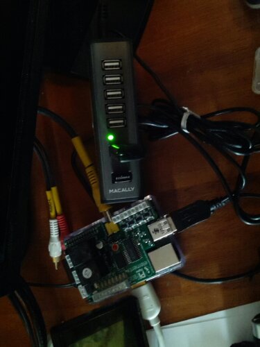
Finally got a delivery from China.  It is the new Arduino Mega 2560 R3 compatible MCU along with a the v2 Sensor Shield.  (this combination had the same pin to usb short I discussed in an earlier post.  Be sure to check that post for the fix or it will fry your mega 2560! (Arduino Mega 2560 shorts against v2 Sensor Shield)
 It took a couple weeks to be delivered,  but the price is less than a quarter of what the cheapest price vendors are offering it here in the U. S..  Not only do a lot of local vendors order them from china,  but a lot of auction sellers will take your money and have it drop shipped from china.  Well worth it to do some research and cut out the middle-man! 


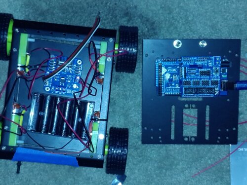
Now that I started to put the components into the battery box,  it is getting very tight with the new SLA 12Ah 12v battery.  The solution is to build a multi-level control board that will slip right in beside the battery. Seems like it works very well,  but it might get a little tight after I start adding sensors and more wiring. 

Thursday, October 3, 2013

Hobby RC remote for testing the Lawnbot!

I've been stuck indoors, unable to work on the mechanical parts of our robotic lawn mower.  I took advantage of this time and wired a Futaba FP-R127DF 7 channel Receiver to an Arduino Uno r3 and wrote a few lines of code to see if I could get it to read the signal from a Futaba T6XH-Super PCM1024 6 channel transmitter.  Was a lot easier to get the Arduino to display the signals than it is going to be for me to figure out what they all are.  This is a programmable aircraft/helicopter remote with settings for just about everything.  Ailerons, flap, Swash Plates and mixing of all the signals.  Wish it was a standard RC car remote!  It's going to take some research to program the transmitter.  With what I do know now, I believe I can get it driving the bot. 
 I started out the day knowing nothing about how to read or interpret rc hobby remotes.  I searched and found a real nice tutorial over at sparkfun.  Wasn't as complete as I thought,  but there is additional info in the comments that will help get it working with dual motor controllers.  The actual page is: https://www.sparkfun.com/tutorials/348
 BTW, not sure if the Raspberry Pi running Raspbian allows for enough time slicing in the multi-tasking to be able to poll the serial ports (usb)  for an rc transmitter combo.  I originally started using the Pi to program the Arduino as I always do.  When I opened the serial port monitor to view the signals, the cpu bogged down and brought the entire system to an absolute crawl at 9600bps.  Made it unusable.  Was forced to bring out another machine with an OS that I loathe! If it weren't my kids, I would install linux on it.  If you were to really delay the polling, you may be able to read it, but I would really check into other OSs or distributions if you want to use it with the Pi.  This is one of the reasons I  will be using the arduino with the Pi on this robot. 
 Tomorrow I hope to post some new updates on the chassis.  At the latest I hope to have something actually moving my the end of next week!  
 I also updated the current hardware page.  This is really starting to run together.  I think it's time to separate the parts by project.  That way if you are trying to duplicate something,  you will know exactly what I  did it with. 

Tuesday, October 1, 2013

Large mower-robot chassis progressing quickly !

Here's a quick update since I haven't posted in a bit.  Work is going on daily.  At least a couple hours a day is what I have been trying for.  Lately I  have been working on getting a physical chassis up and running.  What is pictured is a first mock-up of my 3 wheeled mower bot.  
The 2 rear wheels are salvaged, geared drive, dual 12v, 25 amp motors.  Taken from a kid's power wheels ride on jeep.  Along with the dual 45amp mosfets driven H-bridge should be more than enough to drive this bot through any urban environment . 
 The cutter motor is a 25cc, 4 stroke propane string trimmer (weed whacker) motor.  I had built the system around the string trimmer's 18" inch cutter head, but the body size of 18x24 inches is extremely large for my yard and would not only cut the lawn in a couple passes, but prevent me from maneuvering in the tight areas.  So I believe I  will not only shorten the cutter head, but also the overall size by about 2/3rds.
  The next step is to mount the battery box and some of the computer equipment so I  can start testing the base with a 6 channel remote control.  I will be sure to post some videos of this step as well. 
 The next hurdle is going to be cutting up the motor's clutch housing and fabricating a cutter head drive.  Obviously I won't be able to use the 8 foot drive shaft that came with the weed whacker. 
  So anytime I am not posting,  it's not that I have given up on any of this project!  It's more like I am so involved and barely have time to do anything but work on this bot.  I really want it to move forward quickly and have a working, remote controlled chassis in the next couple of days!  (did I mention a contractor has the front of my house torn off at the moment?  Ah,  Busy days!) 

Sunday, September 22, 2013

Raspberry Pi tablet using Tightvnc and Remote Ripple.

Yesterday I showed you how to convert an inexpensive LCD monitor to be powered and run with the Raspberry Pi. My intention for that screen is to run a custom python program which will monitor sensor data and system status of my robot.  But it is much too small for everyday use and I  really don't want to plug it into the HDMI monitor every time I need to change one line of code.  The solution for me is to run a TightVNC server on the Raspberry Pi and Remote Ripple (from the creator of TightVNC. )  on my Nexus 10 running Android.  I can connect to the RPI from Windows, Macintosh, Linux, Android or any computer running a VNC Client program over WiFi. You can then run any program,  change files,  update the system, reboot or halt the RPI as if you were connected to it with a keyboard,  mouse and local monitor with any computer running the client software.  Even a Nexus 10 Tablet! 
So how do you do it? 

 I installed it using the instructions here: http://elinux.org/RPi_VNC_Server


TightVNC is available for free at Tightvnc.com contains the client and server software, is available for free and works on most platforms (except android) .  Remote Ripple client software does work on Android,  requires a very small license fee and is available from the Play Store. 

Friday, September 20, 2013

Hack 4.3 inch tft display to run on the Raspberry Pi's 5v DC supply!


I purchased one of the inexpensive 4.3 inch tft lcd display to use with my Raspberry Pi/Robot. It is set up for 12v DC Automobile voltage, but the hardware can be hacked to run on 5v DC power.  The same power as the USB input on the Raspberry Pi and the logic supply on my motor controller.  I did a search and found instructions for other displays,  but not for the specific one I had purchased.  No brand name on the packaging.  It is model number BWCMO363 and is titled " 4.3'' Color TFT Car Monitor Support 480 x 272 Resolution + Car/Automobile Rear-view System Mirror Display Monitor" on Amazon that uses  the xl1509-5.0 voltage regulator.  Note: do not do any of the following unless you are familiar with electronic components and comfortable with the procedures described.  Altering the components can damage or destroy your display. 
I found the data sheet and confirmed that pin 2 was the 5v out.  Unlike other instructions, I just want to change the power requirements from 12v to 5v.  I am not swapping in a USB cable or any other mods, so it is not necessary to unsolder the voltage regulator chip or even disconnect any other wires except the 12v + Red wire.  We do not need to disconnect the ground since I  am using this cable's Black/ground wire. 
(xl1509-5.0 located center, far right on the circuit board. 
Only 8 leg IC on the board))

This second photo you can see that I moved the red wire from the cable connector on the breadboard.  I moved it over to pin 2 of the xl1509-5.0 voltage regulator and carefully soldered it to the pin 2 leg.  Since there is no longer a voltage in feed,  the regulator should be dormant and does not need to be removed or altered. 


This is my first solder attempt with surface mount components.  As you can see i n the photo above,  this is a very fragile procedure.  I am pointing with needle nose tweezers! My tip of the soldering iron covers at least 2 legs of the voltage regulator.  So just be prepared! 


Since I left a long lead on the wire (less than a 1/8th inch) exposed,  I  put electrical tape above and below the wire to insulate it.  Also, there is no strain relief for the input wires.  (Solder is the only thing keeping it connected to the monitor!)  I used a zip-tie,  tightened around the wire inside the case.  Cut off the tail and when it is closed up, the cable will snap before the solder joint comes under any stress. 


Before closing it up or applying any power, check your connections.  Then the only thing to do is connect it and confirm it works (another note on this model,  connect a video signal/raspberry pi.  Otherwise, without a signal it will not look like any power is connected!) 


It's up and running!  That is my desktop from my Raspberry Pi displayed on this little 4.3 inch tft screen and both of them are running on a regulated 5 volt dc power supply!  The actual monitor I purchased is listed as :

model number BWCMO363 
4.3'' Color TFT Car Monitor Support 480 x 272 Resolution + Car/Automobile Rear-view System Mirror Display Monitor on Amazon.  

Note from the reviews: the model number stays the same,  packaging and design (menu buttons)  do change. 

Thursday, September 19, 2013

Repair Terminals on Hobby DC Motors.


A lot of people think the motor is destroyed when the fragile brass terminal connector that connects the wire to the motor's brush tears off. It happens all the time from wear and tear or even from disconnecting a terminal plug when they are brand spanking new.  Most times there aren't replacements available for a darn good motor that has years of service ahead of it.
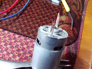
  Here is a quick and dirty fix which is not only a temporary fix, but could be way more secure than the original tab ever was.  First, most often it breaks off at the motor frame and there is no metal to solder anything to. If you are lucky, you have a small gap wide enough to insert a couple strands of thin (stripped 24 gauge or smaller) solid copper wire.  But most there will be no way to clean the existing metal.  Lets change that! (If you can get away without drilling, don't drill! If you get to aggressive, it can destroy the brush terminal!) Take the smallest drill bit you can find, most often that will be 1/16th of an inch. If possible, go even smaller with specialty bits.  We're not drilling through the case, so take it slow with a hand drill or drill press.  I used a hand driven twist drill since you just want to open up/clean the area beside the motor's connector enough for a couple pieces of thin copper wire.
You want to drill straight down beside the existing brush/terminal connection. A power drill will drill a hole too quick and chew the brass brush to bits. I fit 4 small pieces of solid strand copper wire beside the broken brass terminal. Then solder the brass and copper together making a new solid tab. That's it.  Test your motor and you are good to go!
This motor required that both terminals be repaired. Works as good as new!
If you notice the circuit board in the upper photo with 8 mosfet and close to 30 transistors. Our new dual 45 amp motor controller for the upcoming robot! Lots of good stuff coming, stayed tuned!


Monday, September 9, 2013

Homemade GPIO breakout for the Raspberry Pi / PiFace!


My home made adapter allows access to all the GPIO pins while using the PiFace! 

Problem: I have a Raspberry Pi with a Pi Camera.  I would like to install a PiFace to control some of the robot's parts direct from  the Raspberry Pi, but I would also like access to the GPIO pins so I  could also add an arduino via I2C or even SPI.  The Piface does not have a pass-through port or any access to individual GPIO pins (even though you can use 4 PiFace boards together, there is no way to connect them to each other or add any additional hardware.)  I would love to use the PiFace with any other GPIO hardware! 
  My solution: a few inches of ribbon cable,  2x 26 pin (2x13) female plugs and 1x 26 pin (2x13) male plug. A couple dollars and the PiFace is shifted up and a little to the left,  no longer crushing the Pi Camera's cable.  It also allows me to use my original Pi case (can't be used with the stock PiFace) and now I have full access to all 26 pins of the Pi's GPIO port. 
 Tomorrow I will need to mount the board with a couple well placed plastic bolts since the PiFace does not have mounting holes (relied on pin and socket electrical connection of the GPIO to hold it in place!)  This arrangement is so much better than the original configuration!  One added benefit is the space between boards.  I think I will take advantage of it to mount a cooling fan to provide airflow between both boards. 
 You can modify this in many ways,  you could run several male or female plugs to make several GPIO sockets or you could terminate it on a circuit board as I am and build a custom circuit/controller for the Pi.  Make your own sensor shield or just relocate add-on boards.  Very easy and very inexpensive! 

 Tomorrow I plan to assemble a level shifter onto the board shown connected to the GPIO cable.  This will connect an arduino board. I will also start designing a power supply to power the 3 different boards (Raspberry Pi, Arduino 328p and even a Mosfet h-bridge motor controller that is on a slow boat from China.. Literally!  4-6 weeks delivery from China!!!) 
  If it isn't clear what I am doing,  I have some grand plans for a remote robot using both the Raspberry Pi and Arduino.  The build gets bigger with each piece I complete,  so I am going to try and slow it down and get the test platform working well (via Radio Control) and then I  will move on to sensors, communication and automation. 
  
 As always,  if you have any questions on any part of this build, or you have any info that you think will make this easier (or any suggestions), please feel free to comment. 


Saturday, September 7, 2013

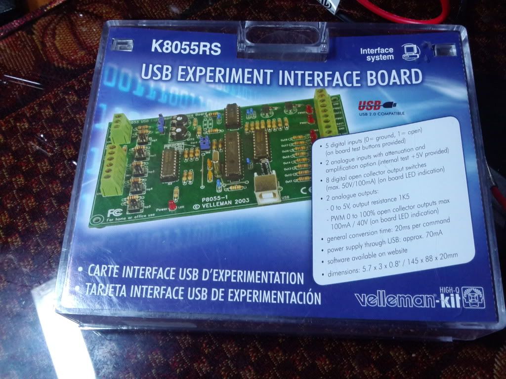
Assembled the k8055 USB controller board!

Completed the assembly of the k8055 USB controller and Experimentation board.  Got it running and tested on my  laptop.
 It seems to be operating properly and tested well.  The next step is to get a Raspberry Pi configured for this controller.  I hope to have it set up and running tests on controlling robot hardware and processing sensor data direct from it this weekend.  I also hope to share some of the harder steps and some videos on creating circuits for use by not only the k8055, but direct sensor processing via the Raspberry Pi's GPIO port as well.

Thursday, September 5, 2013

Robotic power supplies and Raspberry Pi USB controller!

I haven't posted here in a while since I  have not played with my Raspberry-Pi much.  I have been working on a couple arduino controlled robots and this week I made a nichrome plastic bender that is powered by a computer atx power supply that was converted into a robotics lab power supply with extreme accuracy in 1.25-11 volts DC using a LM350 voltage regulator IC.  I'll add some pictures of that below. 
  I had planned to add my Raspberry Pi to the Arduino robot via I2C and a level shifter.  But I think I may have found a way to make the RPI have more direct control.

Wednesday, July 3, 2013

Robot Rover 5 with Arduino Mega2560

I haven't posted an update in a while, that's because I  have been very busy with every spare moment building an Arduino controlled Robot. I haven't given up on the Raspberry Pi. The goal of this project is to actually have the Arduino control the sensors and motors, report the data back to the Raspberry Pi which will be controlling a camera and Internet wifi communication, it will take all the data and instruct the Arduino on what it should do and where it should go.
So far it has been a fun and frustrating process.  As many of my followers know,  I

Sunday, May 26, 2013

Backfeed / problem USB Hub(s) on the RPi!

New Plugable high speed 7 port USB Hub

The first USB 7 port hub had major problems right from the start.  Even though it had a 2 amp power supply and was a package deal item on Amazon along with the Raspberry Pi.  It was a no name hub that would cause the keyboard to miss or repeat keys really bad.   So much so,  that I bought several keyboards while trying to find the problem.  Finally it burned out the USB connection to the Raspberry...  Not on the RPi itself .  The one on the hub.
 So the next one, I went with a name brand and made sure it was on the list of verified working devices for the RPi.  It was the Belkin F4U040 4 port hub.  I used it for a couple weeks before I  started having keyboard problems again.  I found that I could fix it by powering up the RPi first and then powering up the hub.  I also found that it was backfeeding the Raspberry Pi.   If I unplugged the RPi with the hub still plugged in,  the Raspberry Pi stayed turned on!   Not a good situation and could have really damaged the little computer!   I notice now they have it listed under the approved USB hubs, but with a note that it backfeeds.  Then it is listed TWICE under 'problem'  devices!  But it is still 'verified'!
 Well, I have been running my 3rd USB hub for a few days now...  No sign of a power

Wednesday, May 22, 2013

Add a case to your Raspberry Pi Camera!


Add a case to your RPi camera.  Simple, safe and secure storage for your Raspberry Pi Camera. (Read everything and understand it all before starting this yourself.  Any questions?  Just ask!) 
I received my Rpi camera and got nervous just using it. All the warning about static electricity as well as notices not to kink the cable. There is no safe way to set it down since the circuits are exposed.  Accidentally set it on the pi and short out a couple connections and not only is your camera gone, but it could damage or destroy the Pi itself! 
This entry is going to be detailed (long with lots of photos).  So it can show you how I made a case that allows me to use my Pi Camera without worry.  To start, the case I chose is rather large at roughly 3"x2.25" by 5/8" deep. You could get away with a case measuring 1.25"x1.25"x5/8" The reason being it's the smallest case that Fry's electronics had in stock. The cases can be found at most electronic supply stores and online by searching for "plastic electronic project enclosure".  The one I have is for small projects and is designed to hold a remote control... Like a garage door opener. 


First step is to make sure everything is unplugged and that you wear a grounding strap or ground yourself to a cold water pipe to discharge any static. Figure out where you want to place the camera and mark it with a sharp brad or small drill. Since it is plastic,  drill a smaller pilot hole to position the larger 5/16" drill bit. Don't use brad point drill bits (they may tear it up), drill at a slower speed to prevent melting and let the bit do the cutting.  Don't force it to avoid cracking the soft plastic. 

The camera lens should fit flush against the case. You can smooth the edges of the hole with a piece of 180 sandpaper and your finger-tip. Protect the lens on hard surfaces. 


With the camera in place, I marked the screw holes with a very tiny phillips screwdriver, simply twist it a couple times to score/mark the plastic. 


Same drilling procedure with 5/64" drill bits.  I then inserted the 2-56 x 3/4" nylon screws, then the camera board and the nylon nuts.  I didn't have to tighten them down since the screws are the exact size of the breadboard holes.  Just connecting the board to the nylon screws holds it in place.  (if you do tighten the nuts down or use other hardware, be aware of the components! They are very close and it could damage the electronics!) 
Since the screws are too long, I cut them off with wire cutters. (screws were found at Fry's electronics, but I have also found them in the specialty hardware drawers at local home improvement centers) 


I then used a dremel with a cutoff wheel to cut a tab in the back cover and the end cap, just slightly larger than the ribbon cable so it can move freely.  It can even sit on the edge or lay flat without kinking or folding the ribbon cable.  Sand the cut edges smooth with the sandpaper. 
Tighten the cover's screws and you are done! Protected,  self standing and lay flat for storage.   You have a custom camera case! 


If you have any questions, drop me a line in the comments and I will do my best to help you out! 

Wednesday, May 15, 2013

Robotic Camera Turret Controlled by Wii Nunchuk via Arduino Uno!


Been VERY busy this last week.  I explored a little deeper into how to manipulate the real world using the Arduino Uno and a couple of servos.  The control is the 3-axis accelerometer from from a Wii game system. The remote actually does have a thumb controlled Joystick on top and although the video does not show it, I can swith over using the "C" button and control the turret using the joystick. The "Z" button rapidly lights a blue LED.

Wednesday, May 8, 2013

Motion activated Screen Saver in Python on Raspberry Pi


The past few weeks while installing my Raspberry Pi and Gertboard, configuring and testing other people’s software…I have been sitting on an idea for my first project. On one of my run’s to Radio Shack, I found a Parallax Passive Infrared (PIR) Sensor for only $5. Unknown if it would even work with my system (voltage and sensor type), I picked it up with this single idea in mind.
The idea was to have the PIR sensor detect me as I come into the room and turn off the Raspberry Pi’s Energy Saving Screen Blanking.  Well I dived right in and taught myself enough Python to get the sensor up and working (yes, the Parallax Rev. B PIR Sensor will work at 3.3v. (or 5 off the board as well)). I even managed to get the HDMI to engage and Disengage the power saving Screen Blanking. But it is a hardware issue that requires the screen to be redrawn to put the desktop back on the monitor.

Sunday, May 5, 2013

Installing the Gertboard Software and ATmega328P

First I would like to mention a site for anyone new to linux. http://cli.learncodethehardway.org/book/ I consider myself a newbie although I ran a multi-line Dial-up BBS (1200Bps!) on DOS back in the late 80's early 90's and used a linux shell account to import Internet e-mail and Usenet newsgroups for my users.   Now that I am starting with the Pi,  I have to learn the basics all over again.  Anyhow this site is a really quick read, just over an hour and I think I am up to speed with the basic shell commands again.  Someone with no experience with CLI might take a bit longer, but it is a free site and very informative. I  Absolutely recommend it to the beginner. (I am now using the sister site for Python learnpythonthehardway.org/book/ ..looks like it will take a bit longer to complete, but just  as "easy going"!)
Now for what I have been doing the past few days with the Raspberry Pi.  I have fully installed the Gertboard and all of the related software.  It has taken a lot of research and hunting since the software and details of the complete setup are in several different sites.  I read and did ALL of the sample projects in the user manual. (Python Samples, not the "C".  I also got both the RPi.GPIO and the WiringPi for Python versions working so I could try all the examples!)

Wednesday, May 1, 2013

Made a custom case for my Raspberry Pi

Update:
Just received my new Raspberry Pi and the Gertboard!  So here's a picture of the new case with both installed.  Works way better than I could ever imagine!


Original post:


One thing that makes me nervous is working on the RPI and Arduino with all the circuits exposed.  Well I had some acrylic plastic sitting around for the past few year and I had a spare 30 minutes this afternoon, so I cranked out a protyping platform/protective case.  The boards will mount inside so they are secure. All 4 sides are open so I can run wires in and out with no problems. On the very top I think I am going to mount the solderless breadboard.
  The top cover comes off by removing the 4 top nuts.   Maybe make it even easier by using wing-nuts or even barrel-nuts if I can find them. The whole thing measures 8x9 inches and the opening is a generous 2" inches. Enough room for the raspberry pi, an Arduino mega 2560 and a relay board or motor controller.. Can even stack my pi face or Gert board.

Monday, April 29, 2013

Destroyed the SD card socket in my Raspberry Pi.


Micro SD adapter mounted in the Raspberry Pi

When it rains,  it poors! For the first week, I have been chasing a bug on the Raspberry Pi. Where keystrokes from the USB keyboard are missing or are duplicated continously .  This bug is caused by low or no power on your USB hub. Since I have a 2 amp powered hub, I have tried changing devices looking for something that was shorted or power hungry that could be causing it.  The problem was intermittent, so I would have to wait for it to occur to try and solve it. Today it happened, so I replaced the keyboard (yet again) and started wiggling wires. I pulled too hard and yanked it from its case while the sd card was installed. The Raspberry Pi came out of the case ripping the Sd card mounts clips off.  It will no longer hold an sd card. Without an sd card it would not boot!

Friday, April 26, 2013

Arduino Bot is hot... Wait, no.. IT'S ON FIRE!!


image
For 3 nights I stayed up till 3am trying to figure out the insane wiring on this thing and trying to get everything correct. Finally completed it today, typed in some sample code and get ready to test it.  I flip the switch,  The lights come on, a good sign... Then they all go out.  A couple seconds to see if anything is going to happen and....  Nothing.  Damn,  now I have to trouble-shoot and do more research. But wait,  what is that I smell?  Plastic burning?  Yep I smell plastic!  Now I see smoke coming from the wiring/mounting holes.  The power is off so what the heck?  I see more and more smoke coming from the motor compartment and can't get to it because I tightened all the cover screws!  A race to get the cover off and remove the batteries before the whole thing goes up.

Arduino Mega 2560 + Raspberry Pi experimental platform


image
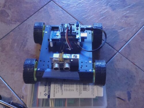
First experiment with a mobile platform using the Raspberry Pi and the Arduino mega 2560.  The kit comes from Sainsmart.com and is a very basic starter kit with the mega 2560, motor driver board and the sensor shield as well as most of the car parts themselves. I purchased them from Amazon.com for about $80 each.  Not bad when the Mega alone sells for $60+ bucks.

Raspberry Pi Installed!


image

Ran into a few problems before even getting into the programming.  I have been reading several books on python while waiting for a delivery of arduino and parts to build a robot.  Anyhow every time I have tried to enter code or update the system, strange things have been happening.  The first keyboard I kept missing keys or getting certain keys stuck in the buffer. so I replaced the keyboard and it seemed to correct the problem.  For the last 2 days I kept trying to download software to install hardware or update the Raspberry Pi itself. My internet connection kept crapping out after 3-4% of a file. (could not keep an internet connection for more than a few minutes)

The journey begins... Into the Raspberry Pi hole!

Rasp_turn_around
I am a 45-year-old father of one with very little experience in programming and even less experience in electronics. My programming experience is limited to C64 and Timex Sinclair 1000 basic when both machines were new and state-of-the-art during my teen years.
Fast forward 25 years and my son wants a Raspberry Pi computer. Helping him set it up and things just start sparking and growing in my mind. The more I explore this device, the more I imagine what it could be used for. Now I own my own RPI setup and have started to explore it as a complete and utter novice.
I understand the device was designed to introduce children into the world of micro-controllers, but I can see it has much more potential. As an older adult, I think it is harder to teach ourselves and to grasp the ideas behind new technologies. But this little device and the community that supports it make it a very powerful learning platform. So I decided to document some of my adventures into the world of this tiny micro controller and see what I can create and unlock. Hopefully you will be able get something out of my experience and insights.
With grand ideas of web-connected robots and RPI controlled CNC or 3d printers to fabricate parts for prototypes, this will prove to be an exciting learning experience for "this old dog".
Well, here we go. Enjoy the ride!